Open205R-C is an STM32 development board designed for the STM32F205RBT6 microcontroller, consists of the mother board and the MCU core board Core205R.
The Open205R-C supports further expansion with various optional accessory boards for specific application. The modular and open design makes it the ideal for starting application development with STM32F2 series microcontrollers.
What's on the mother board?
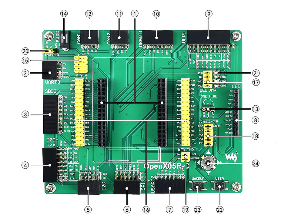
- MCU core board connector: for easily connecting the Core205R
- UART3 interface: easily connects to RS232, USB TO 232, etc.
- SDIO interface: for connecting Micro SD module, features much faster access speed rather than SPI
- I2S2/I2S3/I2C1: for connecting I2S peripherals, such as Audio module
- I2C1/I2C2 interface: easily connects to I2C peripherals such as I/O expander (PCF8574), FRAM (FM24CLxx), etc.
- SPI1/SPI2 + AD/DA interface
- easily connects to SPI peripherals such as DataFlash (AT45DBxx), SD card, MP3 module, etc.
- SPI1 features AD/DA alternative function, supports connecting AD/DA module as well
- USART2 interface: easily connects to RS232, RS485, USB TO 232, etc.
- LCD interface: for connecting touch screen LCD
- ULPI interface: for connecting high-speed USB peripheral (the STM32F205R integrates USB HS controller without any PHY device)
- UART1 interface: easily connects to RS232, USB TO 232, etc.
- CAN2 interface: communicates with accessory boards which feature the CAN device conveniently
- CAN1 interface: communicates with accessory boards which feature the CAN device conveniently
- ONE-WIRE interface: easily connects to ONE-WIRE devices (TO-92 package), such as temperature sensor (DS18B20), electronic registration number (DS2401), etc.
- 5V DC jack
- 5V/3.3 V power input/output: usually used as power output, also common-grounding with other user board
- MCU pins connector: VCC, GND, and all the I/O ports are accessible on expansion connectors for further expansion
- LEDs jumper
- short the jumper to connect to default I/Os used in example code
- open the jumper to connect to custom I/Os via jumper wires
- Joystick jumper
- short the jumper to connect to default I/Os used in example code
- open the jumper to connect to custom I/Os via jumper wires
- User key/Wake-Up button jumper
- short the jumper to connect to default I/Os used in example code
- open the jumper to connect to custom I/Os via jumper wires
- 5V power selection jumper: powered from Core 5V or 5V DC
- LEDs: convenient for indicating I/O status and/or program running state
- User key: convenient for I/O input and/or interact with running code
- Wake-Up button: wake up the STM32 MCU from sleep mode, also used as regular user key
- Joystick: convenient for I/O input (five positions)
What's on the Core205R?
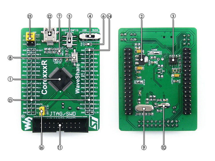
- STM32F205RBT6: the high performance STM32 MCU which features:
- Core: Cortex-M3 32-bit RISC
- Operating Frequency: 120MHz, 150 DMIPS/1.25 DMIPS/MHz
- Operating Voltage: 1.8V-3.6V
- Package: LQFP64
- Memories: 128kB Flash, 64+4kB SRAM
- MCU communication Interfaces:
- 3 x SPI, 4 x USART, 2 x UART, 2 x I2S, 3 x I2C, 1 x SDIO, 2 x CAN
- 1 x USB 2.0 HS/FS device/host/OTG controller with dedicated DMA, on-chip full-speed PHY
- 1 x USB HS ULPI (external PHY required)
- AD & DA converters: 3 x AD (12-bit, 1μs, shares 16 channels); 2 x DA (12-bit)
- Debugging/Programming: supports JTAG/SWD (serial wire debug) interfaces, supports IAP
- AMS1117-3.3: 3.3V voltage regulator
- MIC2075-2: onboard USB power management device
- Power supply switch, powered from 5Vin or USB connection
- Boot mode selection, for configuring BOOT0 pin
- Power indicator
- VBUS LED
- Reset button
- 25M crystal
- 32.768K crystal, for internal RTC with calibration
- JTAG/SWD interface: for debugging/programming
- USB connector, used for establishing USB communication between PC and the STM32 development board
- MCU pins expander, VCC, GND and all the I/O pins are accessible on expansion connectors for further expansion
- 5Vin pinheader, 5V power supply is required when using USB HOST/OTG
- USB jumper
- short the jumper when using USB
- open the jumper to disconnect from related I/O port
- VBAT selection jumper
- short the jumper to use system power supply
- open the jumper to connect the VBAT to external power, such as battery.
Package contains:
- Open205R-C development board x 1
- PL2303 USB UART Board (mini) x 1
- USB type A plug to mini-B plug cable x 1
- USB type A receptacle to mini-B plug cable x 1
- 4-pin 2-pin wires pack x 1
- USB power cable x 1
- User Guide CD x 1
- Ethernet Cable [Extra Add From Package]
Click here to know more about this product.


.jpg)